4 simple steps to simulate a horn antenna

Using simulation software to simulate a horn antenna offers a number of advantages:
– Significantly reduce design and prototyping time
– Quickly explore different configurations and test
scenarios before manufacturing a real prototype
– Reduce design costs
– Speed up product development
– Offer more efficient solutions tailored to customer needs.
Modeling a horn antenna involves understanding the physical phenomena involved in the propagation of electromagnetic waves, and the equations that govern them.
Let’s take a look at the various steps involved in simulating a horn antenna using our CAPITOLE RF software.
1 - Importing the model into Capitole
2 - Meshing and calculation
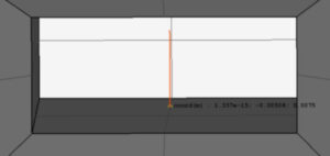
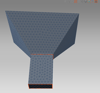
3 - Calculating electromagnetic fields
This is a voltage generator positioned at the region (corresponding to the blue zone on the figure) (base of the monopole).
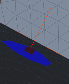
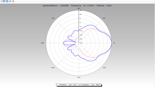
We then carry out a far-field calculation in two main planes corresponding to the following two figures:
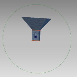
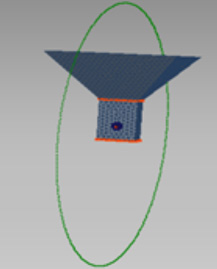
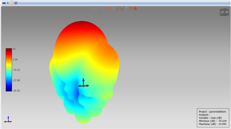
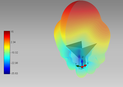
And on a sphere, as shown in the diagram below:
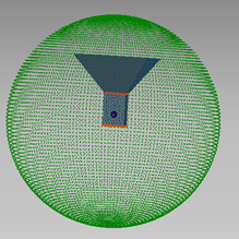
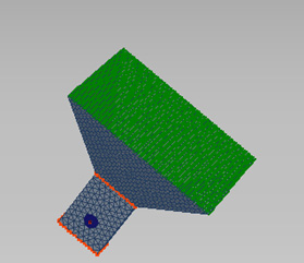
Calculations are performed using a solver of the method-of-moments type, in simple precision.
4 - Post-processing of results and visualization
Post-processing and analysis of the results allows you to visualize :
- The radiation pattern of this horn antenna in its 2 main planes
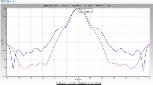
- The 3D radiation pattern with an indication of the maximum gain of this antenna, which is of the order of 15 dBi
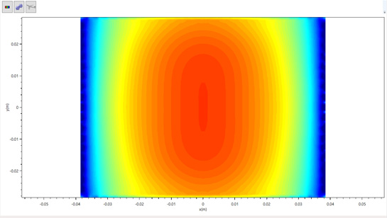
And finally, the distribution of the OY component of the electric field in the plane of the horn aperture, which corresponds to the near-field radiation of this antenna.
Conclusion
This article guides you through the essential steps of simulating a horn antenna on our simulation software. In this guide, you’ll learn how to configure antenna parameters, import models and perform accurate radiation pattern analysis.
Thanks to our simulation software, you now have the tools you need to optimize the design of your horn antenna and evaluate its performance, even before going into the manufacturing phase. This approach will save you valuable time and resources, while guaranteeing high-quality results.
CAPITOLE offers you total transparency.
You’ll know exactly what’s behind each feature, thanks to our detailed documentation of implemented models. You can also import your own data, be it 3D models, antenna radiation patterns or material characteristics. You’re in the driver’s seat!
With CAPITOLE, you have the unrivalled support of Nexio. The first year’s support is included in the price of the license, providing you with quality assistance for all your questions and needs.
And if you want to go even further, Nexio offers additional services such as template creation and product customization to meet your exact requirements.
Don’t settle for less. Choose CAPITOLE and discover an open, flexible software solution that puts the power in your hands.
Our experts are on hand to provide you with expert advice.