Antenna placement on a target drone

This document presents a study of antenna placement on a target drone used in the military field.

This type of drone has been around for many years, and is used to train air defense systems. The drone simulates a missile, allowing a fighter pilot to practice firing it. It is launched by a catapult from the ground and can fly for over an hour at an altitude of 7,000 m at a speed of 200 km/h.
A new active radar system has been developed by LUN’TECH [2] for integration on this type of drone. It consists of two antennas, one receiving and one transmitting. The two antennae are located on the underside of both wings and operate on X-band frequencies (8 to 12 GHz).
The customer’s requirements:
– Evaluate the modification of the antenna radiation pattern with the drone structure
– Optimize the placement of the antennae on the drone
The solution implemented was to model the antennae and the drone, then use simulation software to calculate the radiation pattern of the antennae alone and then in the presence of the drone.

1. Antenna model

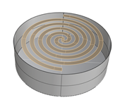
The antenna is an Archimedean spiral with a cylindrical rear cavity.
This antenna is frequency-independent and is therefore often used for broadband applications. The antenna diameter is of the order of 30 mm.
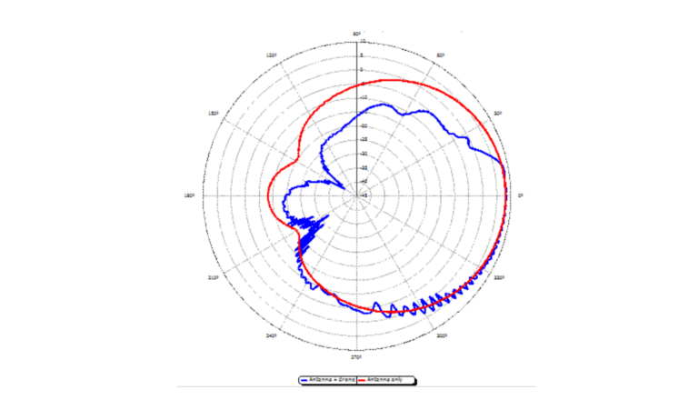
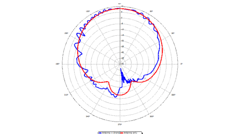
The antenna is placed on a cylindrical cavity which acts as a reflector, to obtain a unidirectional pattern and higher gain.

Figure 1 - Measurement antenna model

2. Target drone model

For the model of the target drone, we used a CAD model of the Meggitt BTT-3 Banshee [1]. azimuth from 0 to 180°. The zero azimuth corresponds to the incidence on the tip. The angle of elevation is zero.

drone
Figure 2 - drone dimensions

The CAD file was in IGES format. Simplifications were made using Rhinoceros 3D CAD software.

3. Using CAPITOLE-RF

An initial simulation of the spiral antenna alone has been carried out. It provides a reference radiation pattern.

Figure 3 - Spiral antenna radiation pattern only
Figure 4 - Spiral antenna radiation pattern only

Next, the antenna is placed on the drone model to assess the impact of the fuselage on the radiation pattern.

avion simulation
Figure 5 - 3D radiation diagram with drone
diagramme
Figure 6 - Antenna radiation pattern with and without drone - Theta cross-section, Horizontal plane
diagramme
Figure 7 - Antenna radiation pattern with and without drone - Phi section - vertical plane

Conclusion

This study deals with the calculation of the radiation pattern of an antenna on a drone. NEXIO’s CAPITOLE-RF simulation software was used.
The difficulty here was that the operating frequency of the antenna was very high (10 Ghz), and with a drone whose length is 3 meters and wingspan 2.80 meters, the calculation took up around 200 GB of memory. Thanks to a calculation server available from Nexio, the project could be simulated in just under 5 hours.
From the calculation results, it can be seen in Figure 6 that the diagram is strongly modified by the drone structure. This behavior is logical, since the fuselage acts as a reflector. Further simulations can be carried out to find the ideal antenna placement, i.e. the one for which the change in the pattern is the smallest.
These results show the usefulness of simulation for antenna integration on a structure: on the one hand, several placement configurations can be studied easily, and on the other hand, it is difficult and expensive to make an antenna radiation pattern measurement with a drone. Measuring equipment such as anechoic chambers are limited in size, and the drone’s weight would require the use of a positioner adapted for heavy loads.

References

Test CAPITOLE RF

Explore the possibilities offered by CAPITOLE RF today.

Scroll to Top