First, we carry out an initial simulation without seeking to optimize antenna matching.
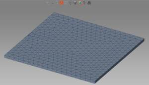
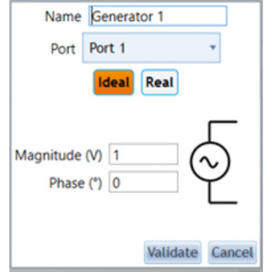
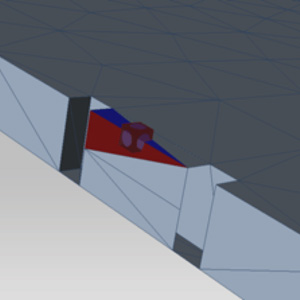
In this non-optimized configuration, a calculation is performed using a solver based on the method of moments to determine the reflection coefficient.
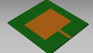
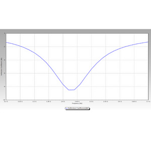
The antenna designed to operate around 2.4 GHz has a reflection coefficient of around -9dB, which is not optimal.
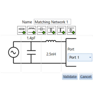
To improve the antenna’s matching performance, a matching circuit is added, consisting of a schematic including a 1.4 pF capacitor in parallel.
The antenna designed to operate around 2.4 GHz has a reflection coefficient of around -9dB, which is not optimal.
To improve the antenna’s matching performance, a matching circuit is added, consisting of a schematic including a 1.4 pF capacitor in parallel.
Capitole’s “ad matching networks” function is used to achieve this improvement.
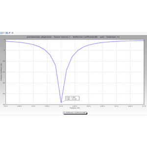
Once the calculation has been run again with this new configuration, the result shows a curve with a much lower reflection coefficient level in the antenna’s operating band.
At 2.4 GHz, the reflection coefficient is now close to -30 dB, confirming the antenna’s much better adaptation.
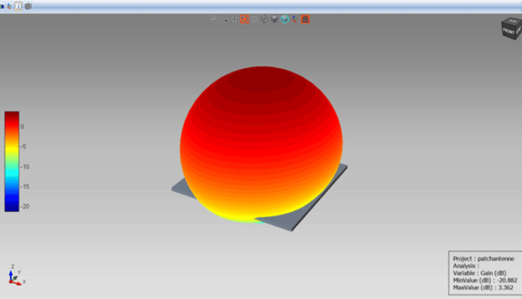
Optimizing patch antenna matching through simulation is an essential process for ensuring efficient signal transmission.
With our simulation software, you can explore a wide range of configurations and parameters to improve your antenna’s performance.
Using CAPITOLE RF will enable you to create high-performance patch antennas capable of meeting the most demanding communication requirements.