Study of different types of coupling using 3D numerical simulation

The study of electromagnetic coupling phenomena is of crucial importance in many fields of engineering, including electronics, telecommunications, energy, automotive and many others. Electromagnetic coupling refers to the interaction between electromagnetic fields emitted by different components or systems, which can lead to undesirable effects such as interference, disturbance or performance degradation.

With this in mind, 3D numerical simulation is an indispensable tool for studying and evaluating various types of electromagnetic coupling. This approach enables detailed analysis of electromagnetic interactions in complex and varied environments, providing insight into phenomena that are often difficult to grasp using analytical or experimental methods alone.

The aim of our studies is to explore different types of electromagnetic coupling using 3D numerical simulations: crosstalk coupling and field-to-wire coupling.

1 Case study 1: Crosstalk coupling

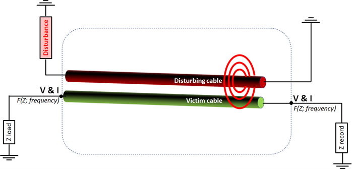
Crosstalk occurs when an electrical signal propagates along one conductor (called a disturbance cable) and induces an unwanted signal on an adjacent conductor (called a sensitive cable). This phenomenon is common in multi-conductor cables, and can lead to electromagnetic interference between the different conductors.

Numerical simulations aim to quantify the level of crosstalk between conductors, identify areas at risk of interference and explore ways of reducing crosstalk coupling, for example by altering the distance between conductors or using appropriate shielding techniques.

Figure 1: Crosstalk representation

2. Case study 2: Field-to-cable coupling

Field-to-cable coupling occurs when external electromagnetic fields induce currents or voltages in exposed cables, which can lead to interference or damage to electronic systems.

Numerical simulations help us to understand how cables react to external electromagnetic fields, to identify areas susceptible to interference and to explore ways of protecting cables from unwanted effects, for example by using suitable shielding techniques or modifying cable routing to minimize coupling.

Figure 2: Field/Cable coupling diagram

2.1 Methodology

The main methodological stages are completed (modeling of structures and cables, definition of stressors (voltage/current or wave), parameterization of observables, etc.), enabling concrete cases to be launched using the co-simulation of 3D solvers and circuit simulators from standard tools on the market.

Figure 3: Ethernet cable model (twisted pair)
Figure 4: Diagram of crosstalk coupling on a coaxial cable

3.conclusion

In conclusion, these studies aim to provide in-depth insight into electromagnetic coupling phenomena through 3D numerical simulations, thus enabling a better understanding of these complex interactions and the development of effective solutions to guarantee optimum performance and adequate electromagnetic compatibility in various engineering applications.

A propos de l'auteur
Scroll to Top