

When simulation helps to reduce the risk of interference between radio systems on an aircraft
Background:
A French company specialized in maintenance and modification services for civil and military aircraft (MRO) asked for NEXIO’s engineering services to investigate possible disturbances that a new SATCOM system on an Airbus A330 could cause to the aircraft’s other radio systems.
The issue:
Adding a new radio system with its antenna on an aircraft requires an interference analysis to ensure that it will not disturb other systems (VHF, radio navigation, altimetry, radio communication, etc.) also connected to antennas.
According to the standard procedure, analyses and then tests on aircraft are necessary to verify the absence of interference with the various existing equipment.
However, these operations face several problems in implementing the measures:
• Aircraft must be grounded during testing
• The number of systems to be tested can be high and therefore testing can be very heavy
• The difficulty of changing the position of the antenna when performing the tests.
Therefore, Nexio proposed to use electromagnetic simulation for this study.
The realization of the study took place in 4 stages:
• Antenna modeling
• Building of the digital aircraft 3D model (CAD model)
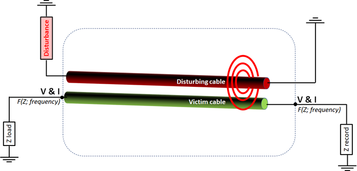
• Simulation of coupling between antennas
• Interference matrix calculation.
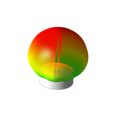
The first step is to model the existing antennas, as well as the new one we want to implement on the aircraft. However, antenna manufacturers provide very little information. In this context, depending on the case, a radiation pattern can be used or a CAD model approaching the antenna is recreated. This model is validated with the specifications provided by the manufacturer or by antenna measurements.
One of the difficulties is to reproduce the behaviour of the antenna in its operating frequency band but also outside this band. Indeed, A VHF antenna operating at approximately 130 MHz can distrub a GPS antenna that operates normally at 1575 MHz, for instance.
The second step is to create a digital 3D model of the aircraft adapted to the RF simulation approach. For this, a mesh is generated from the aircraft’s CAD.
The simulation is performed with electromagnetic simulation software. The choice of the solver depends on the operating frequency of the antennas, the 3D model size and its complexity (e.g., materials). For this study we used a method called «asymptotic», based on the Physical Optics (PO) which is adapted to the big size of the problem. Simulation then allows us to determine the coupling between each antenna.
Finally, the interference matrix uses the previously calculated coupling data and integrates the powers and sensitivities of each system to highlight a margin between sensitivity and the level of spurious signals.
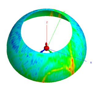
Here is the result obtained:
Simulation interference analysis can be considered as a solution for determining the risks of interference between radio systems on an aircraft with good accuracy.
The quality of the result obtained makes it possible to decide whether the installation is possible or not without incurring significant costs related to a heavy campaign of measurements.
Once the digital model is available, it is possible to vary the position of the antenna on the aircraft in order to find the best compromise, which is impossible during tests on the real aircraft.
Although some tests are essential for final certification, the simulation can reduce this number and thus reduce the downtime of the aircraft on the ground.
Such a study clearly shows the benefit of simulation in terms of reducing costs and delays for the realization of such a project of implantation of a new antenna on an aircraft.